The assembly language is the most basic programming language and corresponds to machine instructions one-to-one, making it the most suitable language for understanding microcomputer operation. Although C-language is also becoming popular in the microcomputer field, studying programs written in the assembly language will be very helpful for developing a program with C-language afterward. The CPU can execute machine instructions only. No matter in which language a program is written, it must be converted into machine instructions in the end. Since machine instructions are collections of 0s and 1s, it is difficult to develop a program directly with machine language.For this reason, assembly language is used since it enables machine language to be expressed in easily understandable alphabets. For example, a machine instruction to add the R0L and R1L as an arithmetic register is expressed as follows in 16 bits:
0000 1000 1000 1001
  In assembly language, it is expressed as follows:
ADD.B R0L,R1L
  A program written in assembly language is referred to as a source program.

4.1 CPU Internal Registers

  Before developing a program with assembly language, you need to know what kinds of registers and functions the CPU has.Figure 4.1 shows the CPU internal registers of the H8/300H.

Figure 4.1: CPU Internal Registers


  The internal registers are classified into general-purpose and control registers.
  The general-purpose registers are used to calculate data and store addresses.
  The control register is further classified into the PC (program counter) to control program progress and the CCR (condition code register) to test conditions.

How to use general-purpose registers

  The CPU has 8 general-purpose registers, each capable of storing 32-digit binary numbers.In addition to 32-bit data, they can also store 16- or 8-bit data.
When 32-bit data is stored, they are described as follows in an instruction, using 8 registers in all:

ER0, ER1, ER2, ER3, ER4, ER5, ER6, ER7

When 16-bit data is stored, they are described as follows in an instruction, using registers as 16 units in all:

E0, E1, E2, E3, E4, E5, E6, E7, R0, R1, R2, R3, R4, R5, R6, R7

When 8-bit data is stored, they are described as follows in an instruction, using registers as 16 units in all:

R0H, R0L, R1H, R1L, R2H, R2L, R3H, R3L, R4H, R4L, R5H, R5L, R6H, R6L, R7H, R7L

This is illustrated in Figure 4.2.
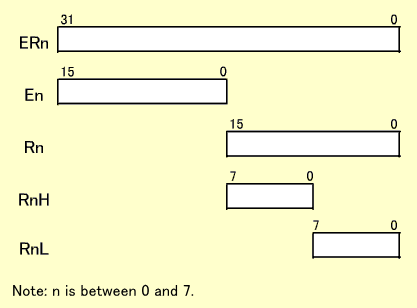
Figure 4.2: General-purpose Register


Example of calculation by general-purpose registers

  In this example, an add instruction is used to show how general-purpose registers are actually used.
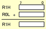
  ADD.B R0L,R1H is an instruction for 8-bit addition. ADD represents "ADDition" and B represents "Byte" (8 bits). The contents of the R1H and R0L are added and the results are stored in the R1H.

  This will not influence the E1 or R1L. Only 8-bit results are obtained. Any 8-bit register is available for this calculation. For example, you can specify the same register like "ADD.B R1L,R1L". In this case, the R1L is doubled.

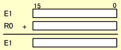
  ADD.W R0,E1 is an instruction for 16-bit addition. ADD represents "ADDition" and W represents "Word" (16 bits). The contents of the E1 and R0 are added and the results are stored in the E1.

  This will not influence the R1.Only 16-bit results are obtained.

  ADD.L ER0,ER1 is an instruction for 32-bit addition.ADD represents "ADDition" and L represents "Long word" (32 bits). The contents of the ER1 and ER0 are added and the results are stored in the ER1.

The 32-bit results are stored in the ER1.


SP (stack pointer)
  A special function has been added to the ER7 as a stack pointer.The ER7 is usually not used for calculation but as a stack pointer. The stack pointer function is described in detail in "Subroutines" and "Interrupt Operations".

PC (program counter)
  n the program counter, the "address of the instruction to be executed next" is always stored and the data is automatically updated every time the CPU reads instructions.Since the addresses are 24 bits, the PC also has 24-bit configuration. Programmers need not pay special attention to how the PC is configured. Every time an instruction is read, the address of the next instruction is automatically stored.
  In the case of the H8/300H, an instruction is always read from an even-numbered address first. This means that an even-numbered address is always stored in the PC (see "Data in the memory").

CCR (condition code register)
  This is used to control interrupts or test conditions.Although it is an 8-bit register, every bit has a different meaning. Interrupt control is described in detail in "Exception Handling".
  This section describes the part used for conditional test. Every time an instruction is executed, the N, Z, V and C bits change to reflect the results. Conditions are tested based on their changes. An instruction to be tested exists separately. The N, Z, V and C bits are called "flags".

N (Negative) flag
: When the execution results are regarded to be a signed binary number, set to 1 if it is negative, or 0 if positive.
Z (Zero) flag
: Set to 1 if the execution results are zero, otherwise, 0.
V (oVerflow) flag
: When the execution results are regarded to be a signed binary number, set to 1 if it overflows, otherwise, 0.
C (Carry) flag
: Set to 1 if execution results in a carry or borrow, otherwise, 0.

  Conditional test in a program is performed by these four flags. Any condition can be tested using them.

Conditional test using the CCR

  As for two numeric values, X and Y, let's consider how to test their collating sequence.To test the collating sequence, subtraction is used. By subtracting Y from X, the sequence can be tested based on how N, Z, V and C in the CCR change.
  Let's assume that C becomes 1 after subtracting Y from X. This means that a borrow occurred after subtraction. A borrow occurs when X is less than Y. If a borrow does not occur, you can judge that X is equal to or greater than Y.
If Z is 1, X is equal to Y since the subtraction results are zero.If Z is 0, you can judge that X is not equal to Y.
  As described above, the collating sequence can be tested based on C and Z obtained after subtraction. In this case, however, X and Y are assumed to be unsigned binary numbers. If they are signed binary numbers, the N or V flag, instead of C, is used for conditional test.

Data in the memory

  The following describes how to store 8-, 16- and 32-bit data into the memory.
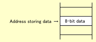
Not only the H8/300H but all 16-bit microcomputers use 8 bits of the memory per address. So, one 8-bit data block exactly occupies one address.


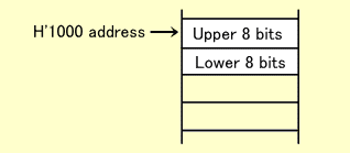
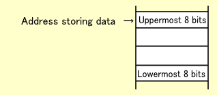
  One 16-bit data block occupies two addresses. The upper 8 bits are stored in a smaller address and the lower 8 bits in a larger one. The smaller one must be an even-numbered address. Although each data block is stored separately in two addresses, the smaller one is regarded to be the address storing the data. For example, "16-bit data in the H'1000 address" means that the upper 8 bits are stored in the H'1000 address and the lower in the H'1001 address.


  In an instruction to read or write 16-bit data, you should specify an even-numbered address (smaller address). If you attempt to read or write 16-bit data by specifying an odd-numbered address, reading/writing will fail. For the reason why this restriction applies, refer to "Connecting CPU to Memory (16-bit Data Bus)".
  In the case of the H8/300H, an instruction is always read in 16-bit units. This means that an instruction must be stored in an even-numbered address. H8/300H machine instructions are composed in 16-bit integral multiples. If the first instruction falls in an even-numbered address, the subsequent instructions also fall in even-numbered addresses.

  One 32-bit data block occupies four addresses of the memory. Since the H8/300H cannot read or write 32-bit data at a time, data are divided into 16-bit units for reading/writing. In this case, the first data must also fall in an even-numbered address. Likewise, the most significant 8 bits are stored in the smallest address and the least significant 8 bits in the largest one.


[Explanation with motion pictures and sound]