7.3.4 Interrupt Operations

(1) Shift to an interrupt handling routine

Figure 7.14 shows three operations performed by the CPU when an interrupt is generated:

Figure 7.14: Interrupt Operations


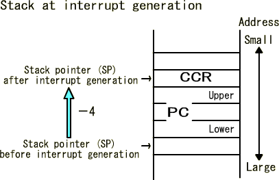
Figure 7.15: Storage of the PC and CCR Values in the Stack

During stacking, the first operation after interrupt generation, the 8-bit CCR value is stored in the address obtained by decrementing the stack pointer by 4 and the 24-bit PC value in the following three addresses. This operation is almost the same as for subroutine call instructions (JSR and BSR instructions) and stores the PC value at interrupt generation as the return address in the stack.
It differs from the subroutine call instructions in that the CCR value at interrupt generation is also stored in the stack. The reason is as follows: since the I bit in the CCR is set to 1 (interrupt disabled) after interrupt generation, the I bit that has been 0 during original program execution is stored in the stack to restore the CCR from the stack when returning to the original program and resetting the I bit to 0 (interrupt enabled).

Figure 7.16: Loading the Interrupt Vector to the PC

During loading the vector to the PC, the second operation after interrupt generation, the vector method is employed as with reset operation.
In the case of interrupts, the start address of each interrupt handling routine is also referred to as the interrupt vector and this 24-bit interrupt vector is stored in the lower three addresses of the four interrupt vector addresses in the memory, which are determined by the interrupt type.
For example, the NMI interrupt vector addresses are the four starting from H'00001C and the IRQ0 interrupt vector addresses are from H'000030. This mechanism enables execution to be moved to different interrupt handling routines according to the type of interrupt generated. For the vector address of each interrupt, refer to Table 7.1 in the following section.

As the last operation after interrupt generation, the CCR sets the I bit in the CCR to 1 to disable (mask) interrupts. This means that after an interrupt is generated to move execution to an interrupt handling routine, any other generated interrupt will be accepted. Another interrupt is accepted only after the current interrupt routine is completed and the RTE instruction, the last instruction in an interrupt routine, is executed.
The NMI interrupt, however, is always accepted irrespective of the I bit in the CCR.


(2) Return from an interrupt handling routine

Figure 7.17: Restoration of the CCR and PC Values from the Stack

You must specify the RTE instruction at the end of every interrupt handling routine and its execution enables processing to return to the original program to continue.The RTE instruction works almost the same as the RTS instruction, an instruction to return from a subroutine. The difference is that the RTE also restores the CCR value stored in the stack.
Although the RTE and RTS instructions have similar names and operations, they are completely different and misuse of them will cause a program to malfunction. Remember to put the RTE instruction at the end of an interrupt handling routine and the RTS instruction at the end of a subroutine.
Also note that if an interrupt handling routine arbitrarily uses a general-purpose register, the value in the register changes when execution is returned to the original program, causing the normal process to fail. To prevent this from happening, develop a program so as to start processing in an interrupt handling routine after storing the general-purpose register to be used in the stack and restore the register from the stack before returning to the original program using the RTE instruction. The PUSH instruction is used to store a general-purpose register in the stack and the POP instruction to restore it. Use these instructions properly to store and restore general-purpose registers.