Although the H8/3048 has an internal ROM and RAM, external memory expansion may be required due to insufficient capacity. The following describes how to connect the memory and CPU and match their speeds using EPROM and SRAM as examples. 13.1 H8/3048 Operating Mode When expanding the H8/3048 memory, you can determine how much memory capacity to be added and how to use the data bus. The mode set pins (MD0, MD1 and MD2) are used to select one of seven operating modes, which determine the uses of the address bus, data bus and read/write signals. Table 13.1 shows each mode:
|
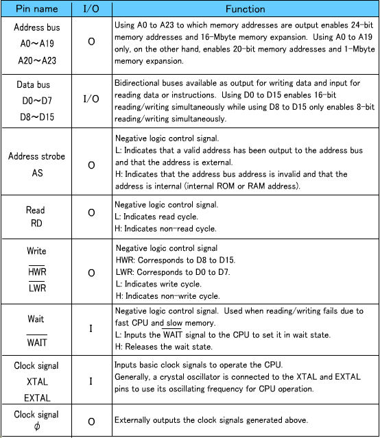
* Status at resetting. It is available as either an 8- or 16-bit bus according to the setting. Since mode 7 represents single-chip mode, no external memory can be added. The internal ROM and RAM are always connected to the CPU through the 16-bit data bus irrespective of the mode setting. "Disabled" in the "Internal ROM" column means that the internal ROM, though it exists, is disabled by being disconnected from the CPU. In this case, an external ROM must be connected. When the internal ROM and RAM are enabled, no external memory can be added to the same address. If the same address is used, the internal memory has priority, disabling reading/writing from/to the externally connected memory. 13.2 Pins for Memory Connection Table 13.2 shows the pins relating to memory connection provided for the H8/3048 and their functions.
|
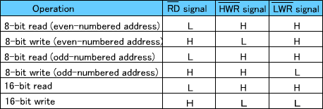
Connected memory size Since there are 24 address buses (A0 to A23), up to 16Mbytes of memory can be connected. If the memory to be connected is 1Mbyte or smaller, only 20 address buses (A0 to A19) are required and the remaining 4 pins can be used for other purposes. Data bus width Since the H8/300H is a 16-bit CPU, it has 16 pins (D0 to D15) for reading and writing 16-bit data. If word data is allowed to be divided into two by the MOV.W instruction, only 8 data bus pins (D8 to D15) are required and the remaining 8 pins (D0 to D7) can be used for other purposes. As described above, the use of pins determines whether the memory address is 16M or 1M and the data bus is either 16 or 8 bits. So you have to figure out the most effective use with the limited number of pins. Address strobe Indicates that an address is valid and that it is external when it is at low level. It is not set at low level if an address is internal (internal ROM or RAM). When the CPU is reading or writing data from/to the internal ROM or RAM, reading/writing is not available externally. The RD, HWR and LWR signals are not changed to low level, either. Read/write signals When the data bus width is 8 bits (RD and HWR are used): Data buses D8 to D15 are used, and D0 to D7 are not. When the data bus width is 16 bits (RD, HWR and LWR are used): |
The RD signal is used as the read signal for both 8- and 16-bit widths, the HWR signal is used for writing to an even-numbered address, and the LWR signal is used for writing to an odd-numbered address. During 16-bit data writing, both the HWR and LWR signals are output. For details, refer to the section describing connection between the CPU and memory.
|