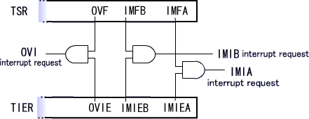
Various limitations apply to the status flag such as conditions for setting/clearing and correspondence to interrupt enable bits.In addition, the status flag is used not only in the A/D converter ADCSR but also in the peripheral functions such as the SCI and ITU described in the following chapters ("R/(W)*" remarks in the following registers represent the status flag).
Fully understand its use here.
 |
 |
 |
Setting of the status flag
- The status flag is set to 1 by the peripheral functions. In other words, it is automatically set to 1 when an event happens on a peripheral function.
(Taking the A/D converter as an example, ADF is set to 1 when the first A/D conversion is completed.) - The status flag cannot be set to 1 using an instruction. For example, the BSET or MOV instruction cannot set it to 1.
- The peripheral functions cannot clear the status flag to 0. In other words, it is not automatically set to 0 even if the event that has set it to 1 is completed.
(Taking the A/D converter as an example, ADF is not set to 0 even if the conversion results are loaded from the A/D data register.) - An instruction must be used to clear the status flag to 0. Simply writing 0 in the status flag, however, does not clear it to 0.
It can be cleared to 0 by loading the entire register once and then writing data to make it 0.
Although the MOV and AND instructions must be executed twice and once, respectively, to clear the flag to 0, the BCLR instruction can clear it through single execution since it loads the entire register, sets the target bit to 0 and writes data in the entire register.
Clearing by combination of MOV and AND instructions MOV.B @ADCSR,ROL ; Loads the entire register AND.B #B'01111111,ROL ; Creates data to set ADF to 0 MOV.B R0L,@ADCSR ; Writes data in the register
Clearing by BCLR instruction BCLR #7,@ADCSR ; Clears ADF ; Clearing completed by this instruction only
Correspondence to interrupt enable/disable bits
Each status flag has corresponding interrupt enable/disable bits. The figures below show the correspondences between status flags and interrupt enable/disable bits.
A peripheral function generates an interrupt request when the following conditions are satisfied. Taking the A/D converter as an example, the ADI interrupt request is generated when the ADCSR ADIE is 1, the first A/D conversion is completed and ADF becomes 1.
 |
 |
 |
Here, a question arises as to when generated interrupt requests are stopped.
Interrupt requests will not be stopped as long as the above conditions are satisfied. This means that interrupt requests are continuously generated even after an interrupt routine corresponding to each interrupt is executed. If the routine is stopped in this state, the same routine is executed again. Taking the A/D converter as an example, ADI interrupt routine execution is permanently continued by the end of the first A/D conversion.
Since the peripheral functions do not automatically clear the status flag or interrupt enable/disable bits to 0, an instruction must be used for clearing. To use the same interrupt repeatedly, the status flag must be cleared to 0 using an instruction to stop interrupt requests.
In summary, remember that the status flag must be cleared to 0 when it is confirmed to be 1 regardless of whether or not you use loops or interrupts.