| 2. DMAC
Operation Modes
This section describes how the DMAC operates in the three modes.
(1) I/O mode
In I/O mode, the DMAC transfers one byte or word on each transfer
request a specified number of times. The transfer cause determines
the transfer direction automatically. An interrupt can be requested
upon completing a specified number of times of transfer. Transfers
are started by an interrupt originating from an internal peripheral facility
or from an external pin. The CPU interrupt handler will not launch
when the DMAC is started by an internal interrupt. When the DMAC
starts, the status flag is reset to suppress the interrupt request.
I/O mode is used to transfer data between a regular internal peripheral
facility and memory.
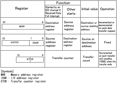
Table 2 describes the register configuration in I/O mode.
Figure 2 shows the I/O mode operation of the DMAC.
| Table 2 I/O mode register configuration |
 |
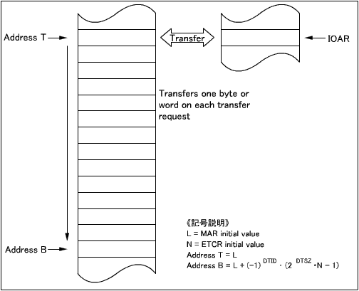 |
| Figure 2 I/O mode operation |
(2) Idle mode
In idle mode, the DMAC transfers one byte or word on each transfer
request a specified number of times as in I/O mode. The transfer
cause determines the transfer direction automatically. An interrupt
can be requested upon completing a specified number of times of transfer.
Idle mode differs from I/O mode in that the memory address is fixed.
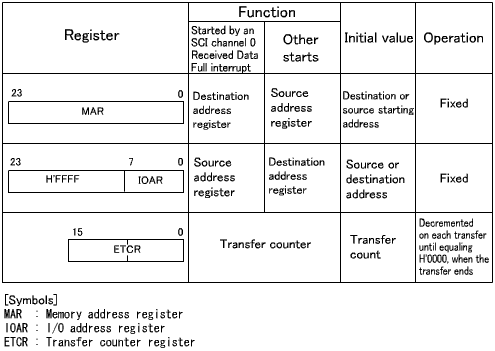
Table 3 describes the register configuration in idle mode.
Figure 3 shows the idle mode operation of the DMAC.
| Table 3 Idle mode register configuration |
 |
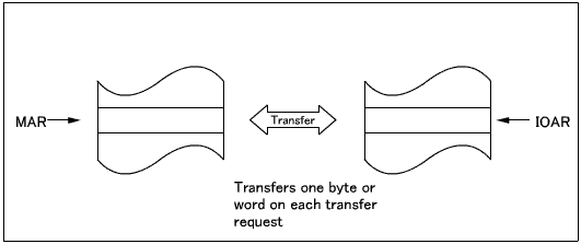 |
| Figure 3 Idle mode operation |
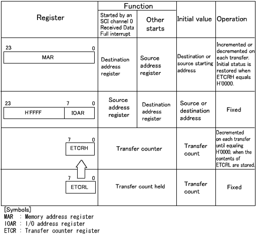
(3) Repeat mode
In repeat mode, the DMAC transfers one byte or word on each
transfer request a specified number of times as in I/O mode. The
transfer cause determines the transfer direction automatically. Repeat
differs from I/O mode in that the transfer counter register is kept in
duplicate, so that the memory address and the transfer count are reset
to their initial values upon completing a specified number of times of
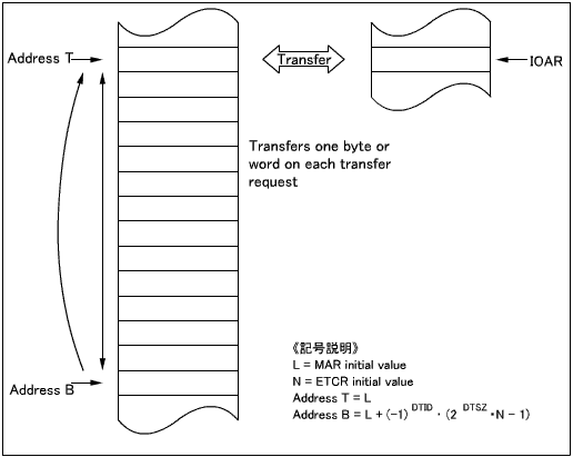
transfer. Repeat mode can be used, therefore, for cyclically using
the same pattern data. Transfers repeat automatically until halted
by the CPU, without raising an interrupt. Because the transfer counter
is 8 bits long, each block has a maximum of 256 words.
Table 4 describes the register configuration in repeat mode.
Figure 4 shows the repeat mode operation of the DMAC.
| Table 4 Repeat mode register configuration |
 |
 |
| Figure 4 Repeat mode operation |
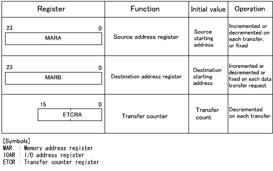
(4) Normal mode
Normal mode is used in conjunction with channels A and B.
The channel A memory address is the source, and the channel B memory address
is the destination. Transfers are started by an auto-request (launched
by a CPU program) or from an external pin. Once the DMAC starts a
transfer by an auto-request, it repeats automatically until the specified
number of times of transfer complete. For auto-requests, transfer
cycles can be selected between burst mode and cycle steal mode for bus
acquisition.
In burst mode, the bus is not returned to the CPU until the
transfer completes. In cycle steal mode, the bus is freed each time
a transfer (one byte or word) completes.
Table 5 describes the register configuration in normal mode.
Figure 5 shows the normal mode operation of the DMAC.
| Table 5 Normal mode register configuration |
 |
 |
| Figure 5 Normal mode operation |
(5) Block transfer mode
Block transfer mode is used in conjunction with channels A and
B. The channel A memory address is the source, and the channel B
memory address is the destination. A specified block size (up to
256 words) is transferred on each transfer request. This transfer
repeats a specified number of tries. Either a continuous or fixed
block area can be selected, so that many patterns stored in memory can
be edited using the DMAC. Either the source or destination can be
specified as a block area.
Transfers are started by ITU channels 0 to 3 or from an external
pin. Once the DMAC starts a transfer, it carries on the transfer
in burst mode until the transfer of one block completes.
Table 6 describes the register configuration in block transfer
mode. Figure 6 shows the block transfer mode operation of the DMAC.
| Table 6 Block transfer mode register configuration |
 |
 |
| Figure 6 Block transfer mode operation |
|


